How does 3D printing work?
It all starts with making a virtual design of the object you want to create. This virtual design is for instance a CAD (Computer Aided Design) file. This CAD file is created using a 3D modeling application or with a 3D scanner (to copy an existing object). A 3D scanner can make a 3D digital copy of an object.
3D scanners
3D scanners use different technologies to generate a 3D model. Examples are: time-of-flight, structured / modulated light, volumetric scanning and many more.
From 3D model to 3D printer
You will have to prepare a 3D model before it is ready to be 3D printed. This is what they call slicing. Slicing is dividing a 3D model into hundreds or thousands of horizontal layers and needs to be done with software.
Sometimes a 3D model can be sliced from within a 3D modeling software application. It is also possible that you are forced to use a certain slicing tool for a certain 3D printer.
When the 3D model is sliced, you are ready to feed it to your 3D printer. This can be done via USB, SD or wifi. It really depends on what brand and type 3D Printer you have.
When a file is uploaded in a 3D printer, the object is ready to be 3D printed layer by layer. The 3D printer reads every slice (2D image) and creates a three dimensional object.
Getting started with 3D Printing
You could start your journey in learning 3D printing by following this Coursera course. However, for the same price you can choose to assemble your own 3D Printer kit. This way you’ll get to know your machine which will help you repairing / adjusting your 3D printer when necessary.If you are interested in going this route, please read our article about cheap 3D printer kits. This article explains what to look for when you’re comparing these kits.
Processes and technologies
Not all 3D printers use the same technology. There are several ways to print and all those available are additive, differing mainly in the way layers are build to create the final object.
Some methods use melting or softening material to produce the layers. Selective laser sintering (SLS) and fused deposition modeling (FDM) are the most common technologies using this way of 3D printing. Another method is when we talk about curing a photo-reactive resin with a UV laser or another similar power source one layer at a time. The most common technology using this method is called stereolithography (SLA).
To be more precise: since 2010, the American Society for Testing and Materials (ASTM) group “ASTM F42 – Additive Manufacturing”, developed a set of standards that classify the Additive Manufacturing processes into 7 categories according to Standard Terminology for Additive Manufacturing Technologies. These seven processes are:
- Vat Photopolymerisation
- Material Jetting
- Binder Jetting
- Material Extrusion
- Powder Bed Fusion
- Sheet Lamination
- Directed Energy Deposition
Below you’ll find a short explanation of all of seven processes for 3D printing:
1 Vat Photopolymerisation
A 3D printer based on the Vat Photopolymerisation method has a container filled with photopolymer resin which is then hardened with a UV light source.
The most commonly used technology in this processes is Stereolithography (SLA). This technology employs a vat of liquid ultraviolet curable photopolymer resin and an ultraviolet laser to build the object’s layers one at a time. For each layer, the laser beam traces a cross-section of the part pattern on the surface of the liquid resin. Exposure to the ultraviolet laser light cures and solidifies the pattern traced on the resin and joins it to the layer below.
After the pattern has been traced, the SLA’s elevator platform descends by a distance equal to the thickness of a single layer, typically 0.05 mm to 0.15 mm (0.002″ to 0.006″). Then, a resin-filled blade sweeps across the cross section of the part, re-coating it with fresh material. On this new liquid surface, the subsequent layer pattern is traced, joining the previous layer. The complete three dimensional object is formed by this project. Stereolithography requires the use of supporting structures which serve to attach the part to the elevator platform and to hold the object because it floats in the basin filled with liquid resin. These are removed manually after the object is finished.
This technique was invented in 1986 by Charles Hull, who also at the time founded the company, 3D Systems.
Other technologies using Vat Photopolymerisation are the new ultrafast Continuous Liquid Interface Production or CLIP and marginally used older Film Transfer Imaging and Solid Ground Curing.
2 Material Jetting
In this process, material is applied in droplets through a small diameter nozzle, similar to the way a common inkjet paper printer works, but it is applied layer-by-layer to a build platform making a 3D object and then hardened by UV light.
Binder Jetting
With binder jetting two materials are used: powder base material and a liquid binder. In the build chamber, powder is spread in equal layers and binder is applied through jet nozzles that “glue” the powder particles in the shape of a programmed 3D object. The finished object is “glued together” by binder remains in the container with the powder base material. After the print is finished, the remaining powder is cleaned off and used for 3D printing the next object. This technology was first developed at the Massachusetts Institute of Technology in 1993 and in 1995 Z Corporation obtained an exclusive license.
Material Extrusion
The most commonly used technology in this process is Fused deposition modeling (FDM)
The FDM technology works using a plastic filament or metal wire which is unwound from a coil and supplying material to an extrusion nozzle which can turn the flow on and off. The nozzle is heated to melt the material and can be moved in both horizontal and vertical directions by a numerically controlled mechanism, directly controlled by a computer-aided manufacturing (CAM) software package. The object is produced by extruding melted material to form layers as the material hardens immediately after extrusion from the nozzle. This technology is most widely used with two plastic filament material types: ABS(Acrylonitrile Butadiene Styrene) and PLA (Polylactic acid) but many other materials are available ranging in properties from wood filed, conductive, flexible etc.
Powder Bed Fusion
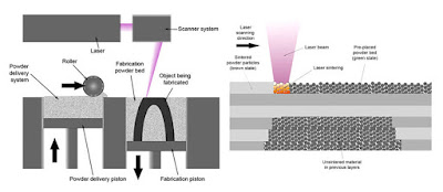
The most commonly used technology in this processes is Selective laser sintering (SLS)

This technology uses a high power laser to fuse small particles of plastic, metal, ceramic or glass powders into a mass that has the desired three dimensional shape. The laser selectively fuses the powdered material by scanning the cross-sections (or layers) generated by the 3D modeling program on the surface of a powder bed. After each cross-section is scanned, the powder bed is lowered by one layer thickness. Then a new layer of material is applied on top and the process is repeated until the object is completed.
Sheet Lamination
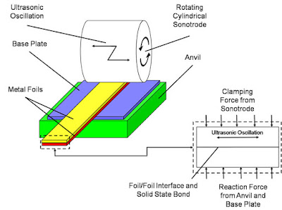
Sheet lamination involves material in sheets which is bound together with external force. Sheets can be metal, paper or a form of polymer. Metal sheets are welded together by ultrasonic welding in layers and then CNC milled into a proper shape. Paper sheets can be used also, but they are glued by adhesive glue and cut in shape by precise blades.
Directed Energy Deposition
This process is mostly used in the high-tech metal industry and in rapid manufacturing applications. The 3D printing apparatus is usually attached to a multi-axis robotic arm and consists of a nozzle that deposits metal powder or wire on a surface and an energy source (laser, electron beam or plasma arc) that melts it, forming a solid object.
Examples & applications of 3D printing
Applications include rapid prototyping, architectural scale models & maquettes, healthcare (3D printed prosthetics and 3D printing with human tissue) and entertainment (e.g. movie props).
Other examples of 3D printing would include reconstructing fossils in paleontology, replicating ancient artifacts in archaeology, reconstructing bones and body parts in forensic pathology and reconstructing heavily damaged evidence acquired from crime scene investigations.
3D printing industry
The worldwide 3D printing industry is expected to grow from $3.07B in revenue in 2013 to $12.8B by 2018, and exceed $21B in worldwide revenue by 2020. As it evolves, 3D printing technology is destined to transform almost every major industry and change the way we live, work, and play in the future.
Medical industry
The outlook for medical use of 3D printing is evolving at an extremely rapid pace as specialists are beginning to utilize 3D printing in more advanced ways. Patients around the world are experiencing improved quality of care through 3D printed implants and prosthetics never before seen.
Bio-printing
As of the early two-thousands 3D printing technology has been studied by biotech firms and academia for possible use in tissue engineering applications where organs and body parts are built using inkjet techniques. Layers of living cells are deposited onto a gel medium and slowly built up to form three dimensional structures. We refer to this field of research with the term: bio-printing.
Aerospace & aviation industries
The growth in utilisation of 3D printing in the aerospace and aviation industries can, for a large part, be derived from the developments in the metal additive manufacturing sector.
NASA for instance prints combustion chamber liners using selective laser melting and as of march 2015 the FAA cleared GE Aviation’s first 3D printed jet engine part to fly: a laser sintered housing for a compressor inlet temperature sensor.
Automotive industry
Although the automotive industry was among the earliest adopters of 3D printing it has for decades relegated 3D printing technology to low volume prototyping applications.
Nowadays the use of 3D printing in automotive is evolving from relatively simple concept models for fit and finish checks and design verification, to functional parts that are used in test vehicles, engines, and platforms. The expectations are that 3D printing in the automotive industry will generate a combined $1.1 billion dollars by 2019.
History
In the history of manufacturing, subtractive methods have often come first. The province of machining (generating exact shapes with high precision) was generally a subtractive affair, from filing and turning through milling and grinding.
Additive manufacturing’s earliest applications have been on the toolroom end of the manufacturing spectrum. For example, rapid prototyping was one of the earliest additive variants and its mission was to reduce the lead time and cost of developing prototypes of new parts and devices, which was earlier only done with subtractive toolroom methods (typically slowly and expensively). However, as the years go by and technology continually advances, additive methods are moving ever further into the production end of manufacturing. Parts that formerly were the sole province of subtractive methods can now in some cases be made more profitably via additive ones.
However, the real integration of the newer additive technologies into commercial production is essentially a matter of complementing subtractive methods rather than displacing them entirely. Predictions for the future of commercial manufacturing, starting from today’s already- begun infancy period, are that manufacturing firms will need to be flexible, ever-improving users of all available technologies in order to remain competitive.
Future
It is predicted by some additive manufacturing advocates that this technological development will change the nature of commerce, because end users will be able to do much of their own manufacturing rather than engaging in trade to buy products from other people and corporations.
3D printers capable of outputting in colour and multiple materials already exist and will continue to improve to a point where functional products will be able to be output. With effects on energy use, waste reduction, customization, product availability, medicine, art, construction and sciences, 3D printing will change the manufacturing world as we know it.
If you’re interested in more future predictions regarding 3D printing, check out The Future Of Open Fabrication.


